EnclosureMetal manufactures custom metal brackets to project drawings. If your assembly needs a bracket with a shaped opening, several mounting holes or more than one formed flange, send us a drawing, sketch or photograph and explain what must fit around it. We can discuss the details needed to evaluate the part and prepare a quotation.
For a bracket with cutouts, the starting point is the assembled position: where it attaches, what passes through the openings and which surfaces must remain clear. These relationships help define the finished shape before material, finishing and manufacturing details are agreed.
Three bracket shapes, different details to confirm
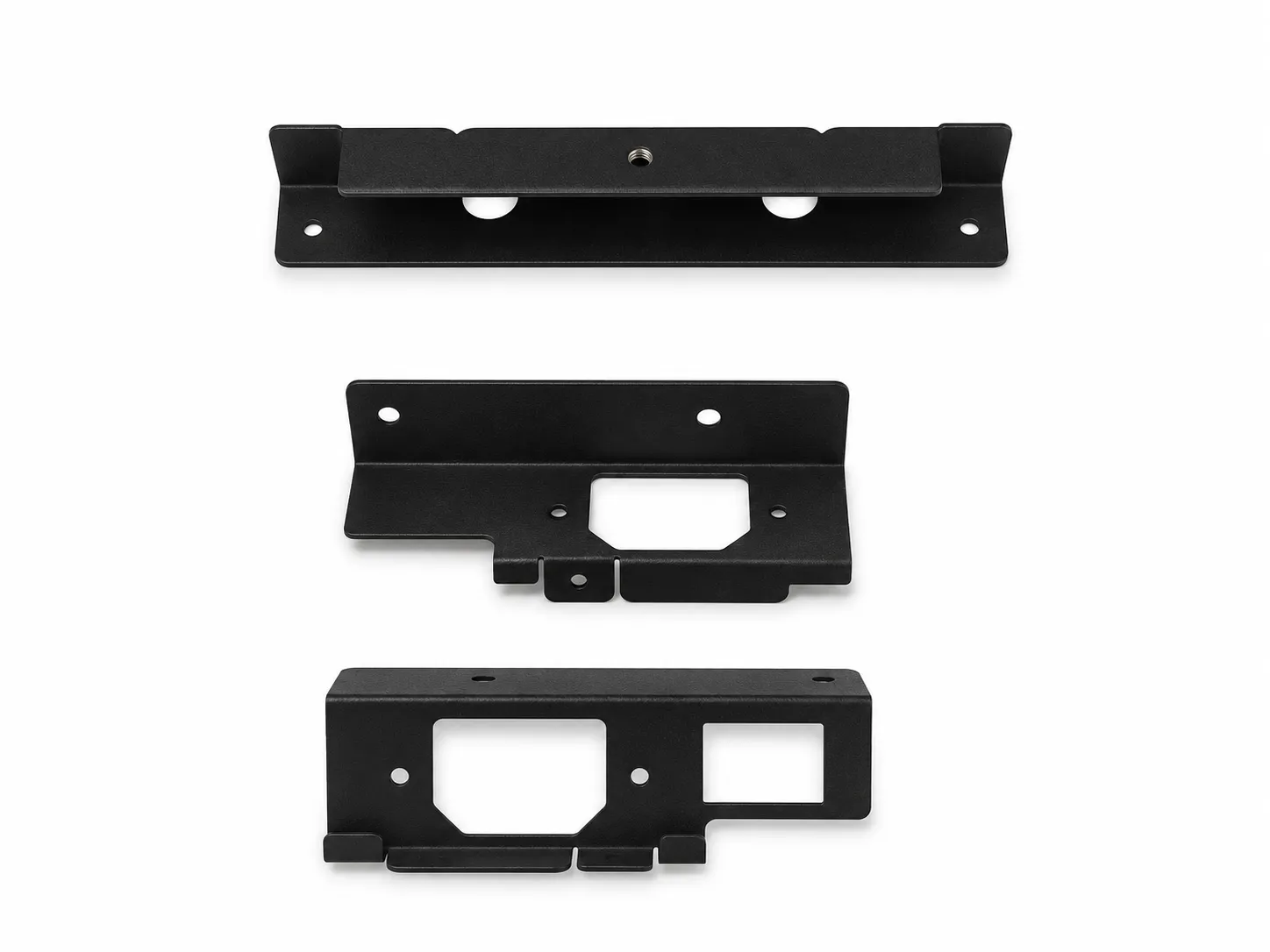
The three black bracket examples shown here combine mounting holes, formed edges and different opening patterns. Their shapes offer useful starting points for discussing a custom part. Choose the features your assembly needs, then define them on your own drawing.
| Bracket example | Visible structure | What to define for your project |
|---|---|---|
| Long bracket | An elongated body, a continuous formed flange, end features and mounting holes. | Overall length, mounting centres, flange height and clearance along the full installed length. |
| Bracket with a shaped opening | An upright flange, a large opening and several smaller holes and tabs. | The opening profile, its position relative to mounting holes, and the clearance around each tab. |
| Bracket with two openings | Two differently shaped openings, mounting holes and formed edges. | What each opening must clear, the space between them and access from either side of the bracket. |
If the bracket must fit an existing enclosure or component, include that mating part in the review. A close photograph helps explain the arrangement; dimensions establish the fit.
Define what each cutout needs to clear
A cutout may provide room for a component, a connector, a cable or an assembly tool. State its intended function instead of specifying an outline alone. For example, an opening that clears a connector body may still prevent the connector from being inserted at the required angle.
Show the occupied space and the installation path. Include any plug, latch or moving feature that extends beyond the main component. If a cable passes through, identify the edge it could touch and whether a grommet or other protection is required.
Keep enough surrounding material for the proposed geometry and service conditions to be assessed. Larger openings and narrow sections between openings need review alongside the mounting arrangement. Include the load direction, attachment points and any vibration requirements so the remaining sections can be assessed.
Specify holes and flanges in the finished position
Use the mounting face or another agreed reference to locate critical holes and openings. When a hole must align with another part, identify that relationship and the fastener involved. State whether it is a clearance hole, a threaded feature or an interface for separate hardware.
For each flange, confirm the bend direction, finished height and required angle. Check both the installed clearance and the space needed to insert and tighten fasteners. A flange can clear the neighbouring part while still obstructing a screwdriver or socket.
Holes and cutouts close to a bend may distort during forming. Their positions, the surrounding material, bend geometry and forming sequence need to be reviewed together. If a feature cannot move, mark it as fixed so that possible changes elsewhere can be discussed. For a broader discussion of these relationships, see our custom metal bracket design guide.
Agree material and finish around the assembly
Specify material grade and thickness when they are established. If they are undecided, describe the support duty, available space and operating environment so that material options can be discussed against the application.
For a black bracket, define the desired colour, texture and gloss separately from the coating or treatment specification. Also identify visible faces, contact surfaces and any areas that need masking. Where a coating is applied, its effect on close-fitting openings and fastener interfaces should be considered in the finished dimensions.
Use an agreed finish sample when appearance is important. An image can communicate the intended look, but the finish requirement should be tied to the agreed specification and sample.
Confirm the sample against the real assembly
A useful sample review follows the way the bracket will be installed: locate it on the mating part, check hole alignment, pass the relevant components through the openings, and confirm fastener access. Then check clearance at the formed edges and any contact points identified in the drawing.
Where strength, vibration or environmental performance matters, agree the relevant acceptance requirements and validation method for the application. Specify those checks separately from visual inspection and trial assembly.
Tell us the sample quantity, expected order quantities and whether the design may change. That context supports a manufacturing and quotation review appropriate to the part. You can view our custom metal bracket service or send the current project details for a quote.