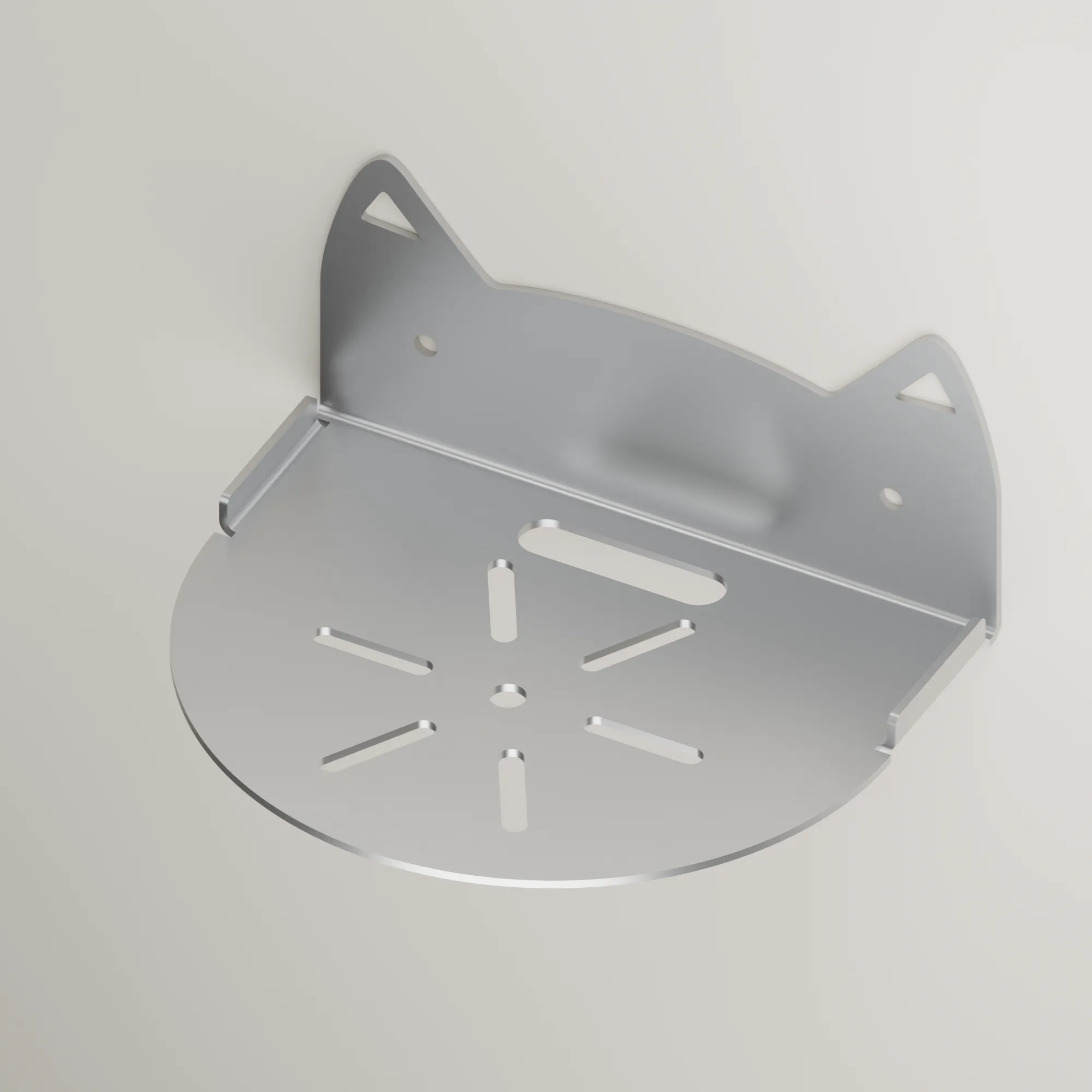
A camera wall shelf needs to match the camera base, cable connector and mounting surface before its outline is chosen. HARVLAND handles custom sheet metal bracket enquiries from drawings, sketches or samples; these three designs show ways to combine a supporting tray with a decorative backplate.
Explore the cat-ear, cloud and mountain designs
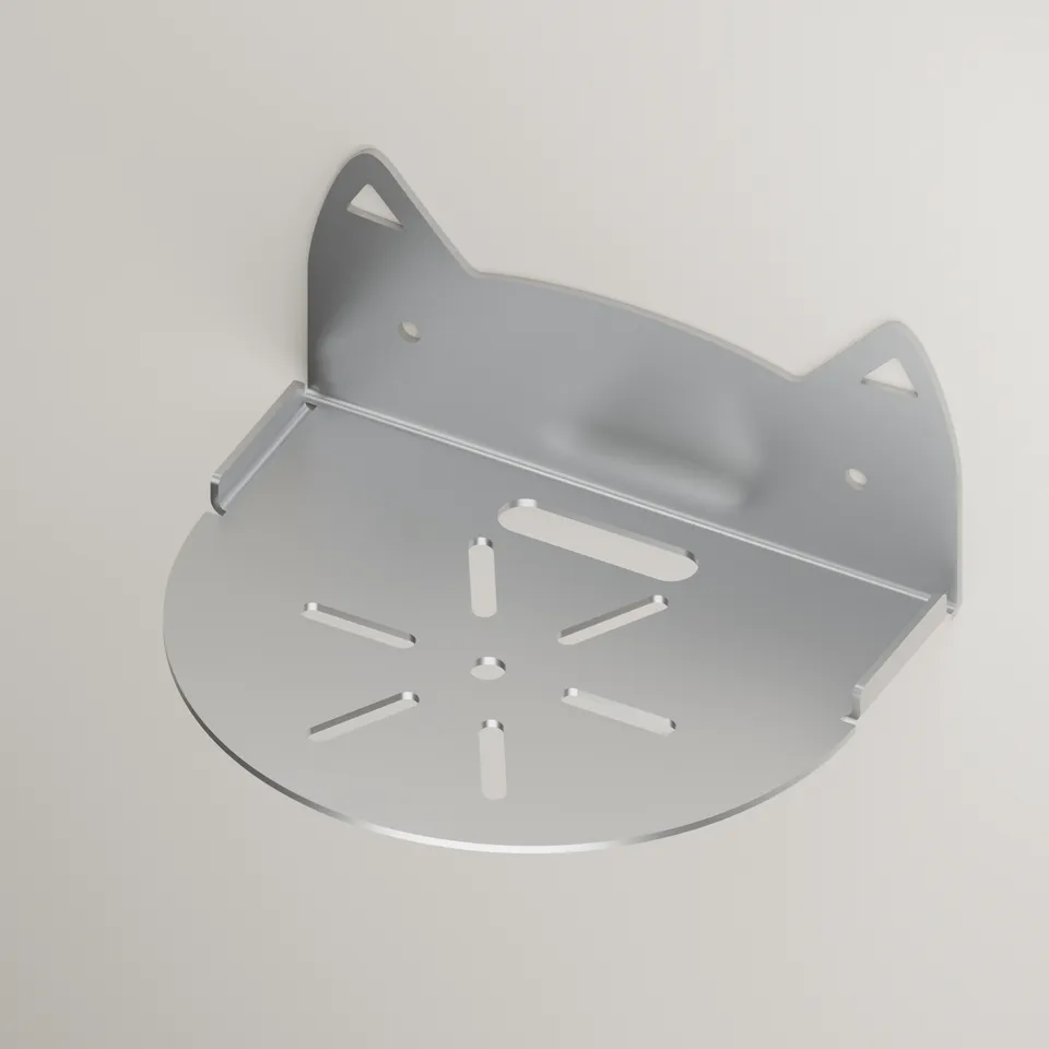
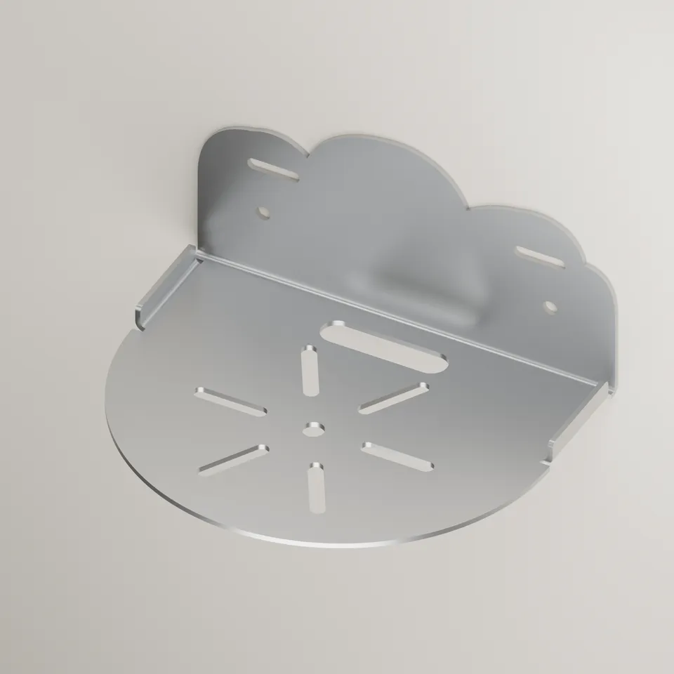
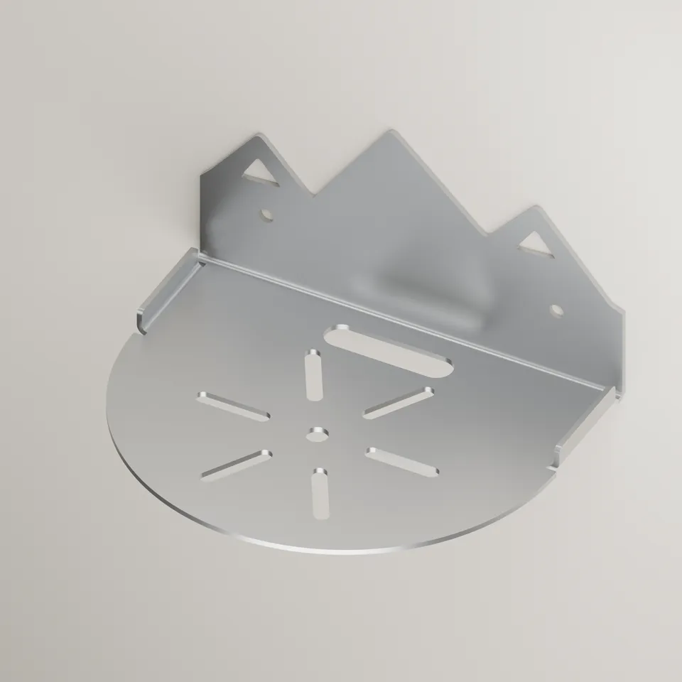
Design preview · drag to rotate, scroll or pinch to zoom.
The cat-ear design pairs two pointed ears and triangular openings with a curved tray. It offers a recognisable silhouette for home camera accessory projects. The ear details can be discussed alongside the overall width and visible branding area.
The cloud design uses a rounded, scalloped backplate. It suits projects seeking a softer outline around an indoor camera. Check the height of the actual camera and its moving parts so the decorative contour stays clear of the lens and movement.
The mountain design uses a ridgeline profile for a more angular appearance. All three models share a wall-facing backplate, a projecting tray, side returns and tray openings. Rotate the models to compare those features; production dimensions and material are agreed through the project drawing.
Size the tray around the camera and its connectors
Start with the camera footprint and the space needed to connect and unplug its cable. A tray that fits the base may still leave too little room behind the device for a rigid connector or a cable bend. Record the required distance from the wall as well as the tray width.
The elongated openings, central round hole and larger rear opening are geometry that can be adapted to a project. Specify whether an opening is for a fastener, a strap, clearance or cable access. Do not assume that one slot pattern fits every camera.
- Camera model, base outline, weight and any moving envelope.
- Required usable tray width and depth, plus rear connector clearance.
- Base screw or retention method, hole centres and access for tightening.
- Cable diameter, connector envelope and the direction the cable must leave.
Confirm the wall fixing and installed behaviour
The backplate has two round mounting holes. Define their spacing around the intended wall fixing and leave access for the installation tool. The wall substrate, anchors, bracket and camera retention must be considered together; the decorative profile alone does not establish a load rating.
- Identify the wall or panel material and the installation location.
- Agree how the camera is retained, including any required pad, strap or base screw.
- Check the assembled sample for fit, tray movement, cable rubbing and the camera’s full viewing or movement range.
Choose the metal, finish and manufacturing route
The illustrated form is a cut and bent sheet metal concept. Laser cutting and press-brake bending are candidate operations for the outline, openings and returns. The final sequence depends on sheet thickness, bend access, required quantities and the accepted drawing.
Select the material and surface finish for the environment and desired appearance. Discuss coating colour, visible faces, edge quality and areas that contact the device or cable. The silver appearance of the renders is a visual treatment; specify the actual alloy and finish separately. If the bracket will be used outdoors, include the exposure and finish requirements in the enquiry.
Prepare a custom camera bracket enquiry
You can start with a camera photo and a sketch showing where it will sit. Choose one of the three outlines or send your own profile. Mark what is fixed and what can change so the tray, backplate and mounting pattern can be reviewed together.
- Send the camera information, installation photo and required dimensions.
- State the outline, colour, logo or packaging requirements and expected quantities.
- Agree a drawing revision and sample checks before confirming the production specification.