Sample specifications and formed geometry
Specify the alloy grade, supplied condition, dimensional tolerances and finish in the final drawing. Define the outside-diameter measurement location and part condition as well as the nominal value.
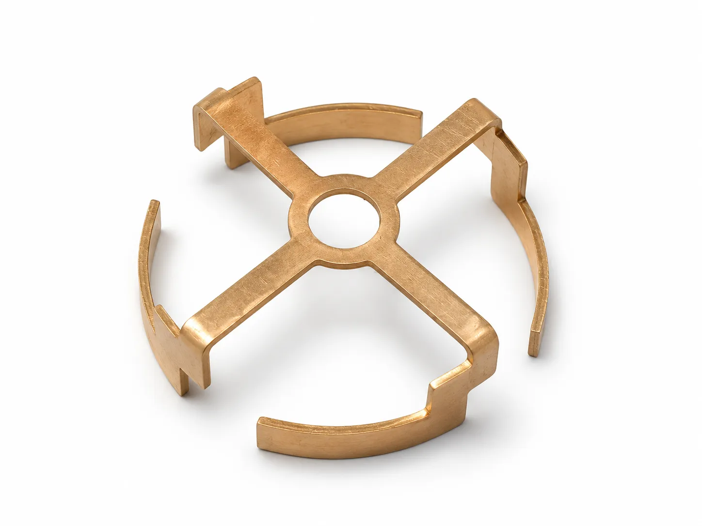
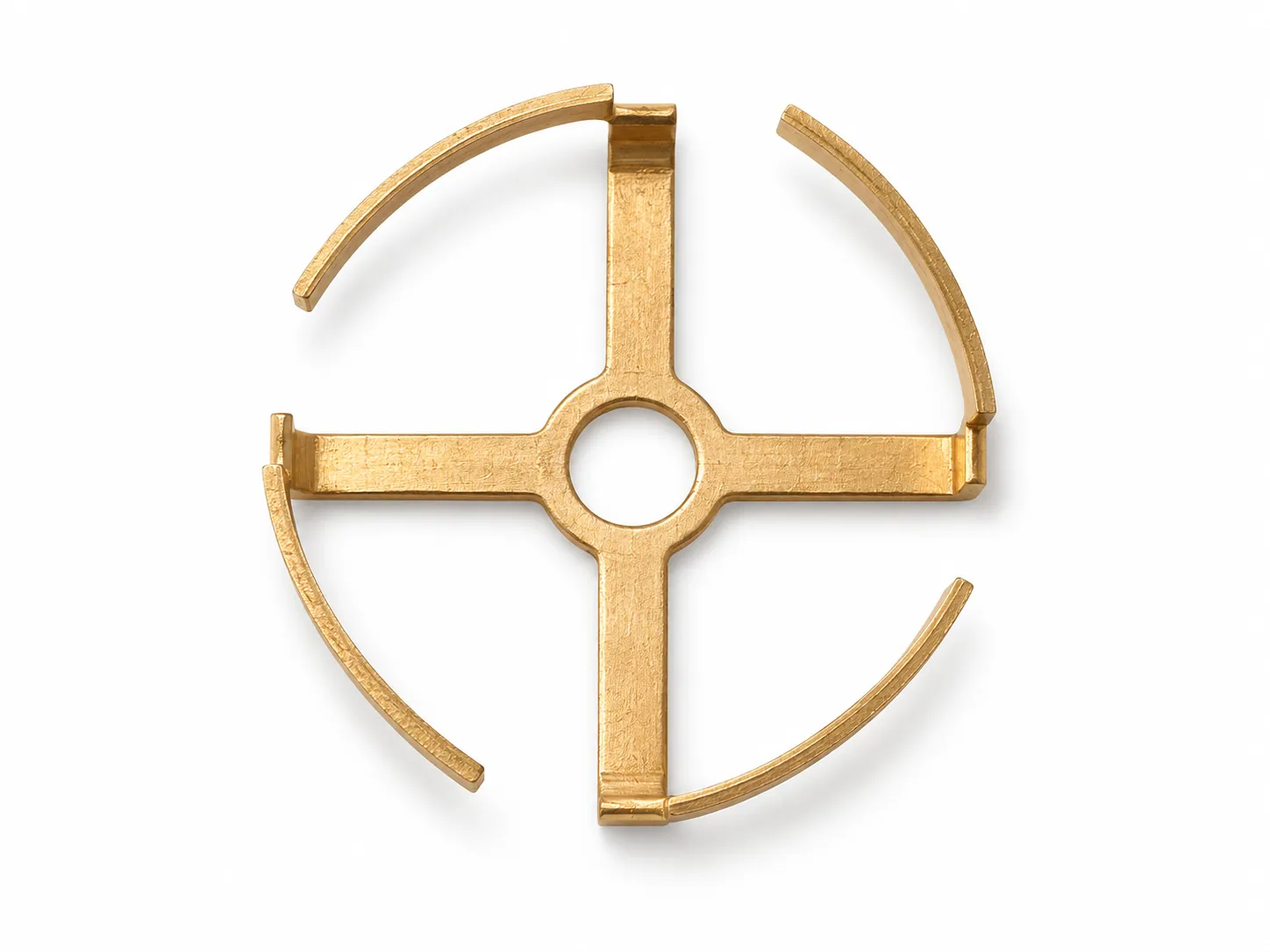
The illustrated antenna terminal has a central circular opening, four radial arms and separated curved sections around the perimeter. The stepped bends place portions of the outer profile above the plane of the arms. Its outline therefore needs both a plan view and a height or section view to describe it clearly.
For a similar part, show the intended position of each curved section relative to the central opening. Include the perimeter gaps and the direction of the steps. If a gap must align with a feature in the mating assembly, identify that relationship on the drawing rather than relying on an overall diameter alone.
Do not leave the role of the central opening implicit. State whether it locates the terminal, provides clearance or serves another purpose. Likewise, mark the actual electrical contact surfaces instead of assuming that every outer curved section is a contact point.
| Item | Supplied specification |
|---|---|
| Material | Phosphor bronze |
| Sheet thickness | 0.5 mm |
| Outside diameter | 18.9 mm |
| Visible features | Central hole, four radial arms, separated curved perimeter sections and stepped bends |
Define the installed condition before discussing changes
Provide a section through the assembled parts or a photograph showing the terminal in place. Mark the insertion direction and any surfaces that must remain clear. This gives the drawing review a practical reference for assessing proposed changes to the hole, arm width, formed height or perimeter profile.
If the design relies on elastic contact, specify the free position and the installed position, plus the required force or acceptance method. If the terminal is rigidly retained, identify the retention method and its locating surfaces. These are different requirements and should not be inferred from a similar-looking sample.
Keep base material and finish as separate requirements
The specified base material for this part is phosphor bronze. Confirm its exact grade and supplied condition for the mechanical and electrical duties of the connection. State the surface finish separately: the warm metal color does not establish that the part is gold plated.
Where the connection needs plating, define the contact area, coating system and acceptance criteria. If another region will be soldered, identify it separately. This lets the finish specification address the relevant connection surfaces rather than using color as the acceptance requirement.
Send an existing material specification if one is available. Otherwise, describe the mating component, operating environment and functional requirements, and mark the material or finish as open for review. Proposed substitutions should be agreed before the drawing is released for manufacture.
What to include in an antenna terminal RFQ
Keep the RFQ focused on the part and its assembly. The following information provides a useful starting package; unresolved items can be listed as questions.
For edges near a mating surface, indicate where burrs or sharp edges would interfere with assembly. Where the curved sections could become entangled or distorted during handling, state how the parts will be loaded into the next operation so packaging can be discussed with the quote.
| Requirement | Information to provide | What it clarifies |
|---|---|---|
| Part definition | Revision-controlled drawing, 3D file or sample photographs | Which version and geometry are being reviewed |
| Central opening and arms | Hole size and position, arm layout, width and thickness | The relationship between the center and the outer profile |
| Formed perimeter | Curved profile, gaps, steps and finished height | The three-dimensional envelope and orientation |
| Mating arrangement | Assembly section, insertion direction and contact surfaces | Where the part must touch, locate or clear another component |
| Material and finish | Grade, condition, thickness and any coating requirements | The specification to use for quotation and samples |
| Acceptance | Critical dimensions, edge requirements and functional checks | What will be checked and under which conditions |
| Supply plan | Sample quantity, production quantities and packaging needs | The requested quotation and delivery scope |
Approve the sample in its mating assembly
Plan sample review around the agreed drawing and the actual mating parts. Check the opening, formed height, perimeter clearance and orientation, then verify the relevant contact or retention function in the installed position.
If electrical measurements or RF checks are required, define the method, assembly condition and pass criteria before sample approval. Dimensional acceptance, contact acceptance and antenna-system acceptance should each have a stated requirement and an assigned test responsibility.
After approval, retain the agreed drawing revision, material and finish specification, inspection requirements and reference sample identification with the purchase specification. Changes to any of those inputs should be reviewed against the same assembly requirements.
Send the part and the assembly context
Send a drawing, sketch or sample photographs, the mating arrangement and your expected quantity through the drawing review and quote form. Mark uncertain dimensions, material or finish choices as questions. For broader process requirements, see custom metal stamping and surface finishing.