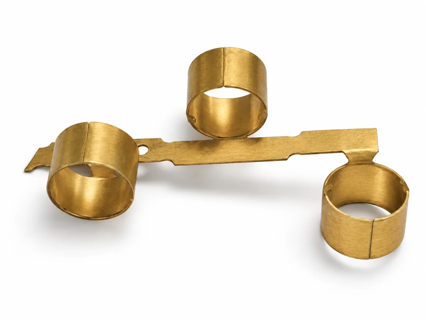
What the sample shows
The sample material has been confirmed as brass. The photographs show three cylindrical features with longitudinal seams and a connecting strip with a hole and notches. The original end use remains unknown. Drawings or manufacturing records are needed to establish whether the strip is a production carrier, whether the hole serves a feed or locating function, and whether the cylindrical features are separated before delivery.
Wrapping or rounding a blank is a candidate route for a cylindrical form with a longitudinal seam. A visible seam does not establish the complete tooling or station sequence. Before developing a custom part, distinguish a loose sleeve, a strip-fed component and a finished connected assembly.
Industries and products worth evaluating
These are application directions for related component families, rather than identification of the photographed sample. Each requires assessment against the actual mating design.
| Industry or assembly | Candidate component family | What determines suitability |
|---|---|---|
| Electronic connectors, control boards and sensor assemblies | Brass contact sleeves or receptacles with connecting tabs | Mating pin, contact zone, retention, mating forces and electrical requirements |
| Industrial harnesses and communication cable assemblies | Inner or mating ferrules for shield termination | Braid, inner/outer ferrule relationship, crimp zone, retention and continuity |
| General equipment and instrument assemblies | Spacers, hole bushings or guide sleeve candidates | Bore fit, axial length, end loading, retention and wear conditions |
Contact sleeves, shielding ferrules and spacers have different jobs
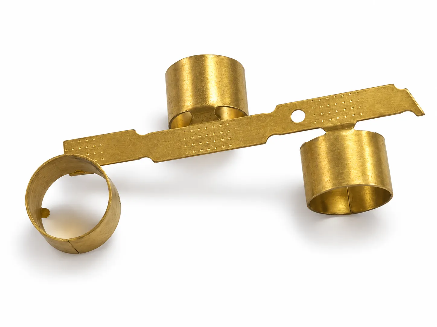
For a mating contact, define where contact is made and which feature supplies the contact force. A cylindrical sleeve fitting over a pin does not establish electrical performance. The design may rely on the sleeve wall, a spring feature or a separate component. Establish insertion and withdrawal forces, contact resistance and applicable temperature-rise requirements for the intended design. Specify the brass alloy, supplied condition and contact surface.
For a braided cable shield termination, evaluate the cable, inner ferrule, outer ferrule and crimp tooling together. The bore must suit the actual feature it surrounds. Retention and electrical continuity need to be checked after termination. A tubular appearance does not establish shielding effectiveness, and a longitudinal seam should not be assumed to provide a seal.
For a spacer, axial length establishes the separation between mating faces. End geometry and wall section affect how clamping loads are carried. If the function changes to sliding guidance, bore variation, surface condition and wear also matter. A general brass sleeve should not be presented as a self-lubricating bearing or pressure-rated tube simply because it is brass.
Define the dimensions and seam in a stated condition
State whether measurements apply to the free part, the part installed in its mating bore, or the completed crimp. Bore size and seam gap can differ between these conditions. Results taken in different conditions should not be treated as measurements of the same drawing requirement.
If the inside diameter controls the fit over a mating component, identify the measurement location and permitted shape variation. If the outside diameter fits into a housing, define that interface. Relate length, end orientation, seam location and permitted gap to assembly function. For a connecting strip, define the hole-to-cylinder relationship and whether the connection remains in the delivered component.
Where plating is required, distinguish contact zones, crimp zones, fit surfaces and excluded areas. State whether dimensions are accepted before or after finishing. A generic finish name does not settle contact, corrosion or fit requirements.
| Drawing item | Conditions to define |
|---|---|
| Material | Brass alloy, supplied condition or hardness, sheet thickness and substitution rules |
| Geometry | ID, OD, length, seam, strip function and measurement condition |
| Edges | Burr direction and edge requirements at entries, cable interfaces and connections |
| Surface | Finish type and location, appearance, dimension stage and inspection basis |
| Delivery | Loose or strip-fed, orientation, protection, quantity and sample approval requirements |
Approve samples against the assembly function
Begin with the agreed mating components: check assembly access, orientation, scratching and looseness, then inspect dimensions that control the function. Electrical contacts need project-defined contact checks; shield terminations need retention and continuity checks; spacers need spacing and loading checks in the intended assembly condition.
Tie approval records to the drawing revision, material condition and surface requirements. If alloy, hardness, thickness, seam or plating changes after sampling, determine which fit and function checks need repeating. Catalog images help explain structure; physical parts, drawings and agreed records support acceptance.
What to send with a custom enquiry
Send HARVLAND a drawing, sketch or sample photographs, and explain what the sleeve surrounds, how it is retained and whether electrical contact or shield termination is required. If the application is still being assessed, start with mating-part photographs, an estimated quantity and the problem you need to solve. The remaining dimensions and sample conditions can then be clarified.
The copper and brass selection guide supports material discussions, while the electronic stamped components page provides a route for electronics enquiries. The manufacturing sequence, finishing scope and acceptance requirements need review against the specific drawing.